Tim Morgan, Private pilot: airplane single-engine...
712 votes by Arlen Cuss, Aaron Chiu, Ian C. Grieve, (more)
All of them? If you're talking about a commercial airliner, then there's hundreds and hundreds. There are big, fat manuals describing what they all do. But, since you asked, buckle up.
Every airplane is different. Unlike learning to drive a car, you can't just hop from one plane to another. A pilot needs familiarization (and in some cases, a whole new type of license) to fly a different kind of plane. Some are piston-powered; some are jet-powered. Some have electrically-driven controls; some are hydraulically-driven. Some have emergency oxygen; some don't. And so on. All the switches, dials, and knobs in the cockpit control the various aircraft systems, and every aircraft has different systems.
Let's take a very popular airliner, the 737. And of course, different 737s are different, so let's just invent a 737 that we can use. A typical one. Here's a photo of a 737.
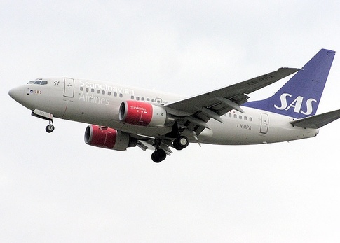
Pretty typical small-body airliner. For our example, we're going to be flying a 737-600, a modernized 737 with glass-cockpit displays and digital avionics.
So, before we can talk about what all the switches in the cockpit do, we need to know what systems the 737-600 has onboard. So without further ado, here is a non-complete list of all the systems that the pilot or copilot might need to manage:
Engine: Our 737 has two CFM56-7 turbofan engines with thrust-reversing capability. The engines are started by an APU (auxiliary power unit) -- the APU is itself a mini-jet engine that is used to start the two big boys under the wing. (The APU is started by the battery, if you're curious.) Fuel flow to the engines is electronically controlled.
Fuel: The 737 has three fuel tanks: one in each wing, and a center tank in the fuselage. Electrically-powered fuel pumps transfer fuel from the tanks to the engines. Each tank has two redundant fuel pumps, for a total of six. The center tank drains first, then the wing tanks. Normally the left center fuel pump sends fuel to the left engine, and vice versa, but there is a cross feed valve that opens to allow the left center pump to provide fuel pressure to the right engine in the event the right center pump fails (or vice versa).
Hydraulics: The engines power three redundant hydraulic systems (systems A and B, and the standby system) which actuate the flight controls (elevators, rudder, ailerons) that maneuver the aircraft in flight. The hydraulic system also powers the landing gear, flaps, and slats, thrust reversers, as well as a few other minor things. System A and B each power a subset of the preceding list, with the standby system providing emergency hydraulic power to the critical systems only.
Electrical: Each engine (including the APU) has its own generator that can power the aircraft's electronics (lights, avionics, galley, in-flight entertainment, etc.). When the engines are off, the aircraft uses an onboard battery to power its systems. There is also a standby battery in the event the main battery is drained. The aircraft can also accept external ground power from a mobile generator. Each electrical source (battery, generator, ground power) can be hooked up to one of two transfer buses that move the electricity to aircraft systems. Typically in flight each engine generator is hooked up to one of the transfer buses. In the event one electrical source (APU, battery) must power both transfer buses, a bus tie system connects the two buses.
Bleed air: Bleed air (siphoned from each engine) powers the air conditioners and anti-ice system, and pressurizes the hydraulic and fuel pumps. The airplane is split into two separate "zones" which can have their own temperature settings. The aircraft can also accept external air from a mobile air cart.
Oxygen: The 737 has two independent oxygen systems -- one for flight crew and one for passengers. In the event of depressurization, the oxygen masks will drop and oxygen canisters will supply pressurized oxygen to the passengers and flight crew.
Navigation: The 737 is equipped with two independent GPS antennas and three IRUs (inertial reference units). An IRU is a gyroscope that records changes in acceleration. By integrating these changes over time, the airplane can track its position, though it gets increasingly inaccurate over time.
Radios: The 737 has three communication (COMM) radios and three navigation (NAV) radios. The COMM radios let the pilot talk to ATC and the NAV radios let the pilot navigate to or from ground radio navigation stations. There's also an onboard weather radar that sends out radio waves ahead of the plane looking for storm clouds.
OK, let's get started. I'll start with the pilot's side of the main panel.

The two main displays in front of the pilot are the PFD (primary flight display; left) and ND (navigational display; right). The pilot and copilot each have a set, and there is a pair of shared DUs (display units) in the center (arranged top-and-bottom). Each can independently display one of a few different screens of information. In the above picture, the top DU is showing engine information and the bottom DU is blank.
The information shown on the PFD is the airspeed tape (left side), the attitude indicator (center -- shows the sky and ground pictorially), the altitude tape (right side), and the rate-of-climb indicator (far right). Along the top, the current autopilot mode is shown (autopilot is currently off). On the bottom is the heading indicator. The yellow text are some warnings and the green text is the altimeter setting (more on that later). The purple text is the autopilot speed and altitude settings (more on that later too).
The navigation information shown is the current heading (solid line) and the course dialed into the FMC (flight management computer; more on that later -- it's the dotted purple line). Two white blocks of text show information about the next waypoint and and some general position information. The green text shows information about how accurately the jet can guess its position.
The engine information shown: On the top left are two dials; they indicate the N1 setting for the left and right engine. N1 is a measure of engine power -- at 100% N1, the engine is producing maximum power (right now the engines are at 22.5% N1). The second row shows the engine's EGT (exhaust gas temperature, currently 411 °C), another measure of engine power and also an important thing to monitor -- if the exhaust gas is too hot, you're in trouble. To the right of the dials is a grid where engine warnings would pop up. On the bottom right are the fuel gauges; it shows the fuel in each of the three tanks and the total fuel onboard (40,200 gallons).
Between the top DU and the pilot's ND are the standby flight instruments. In the event that the PFD fails, the pilot can still get critical flight information from these backup instruments. The top one is the standby flight display -- it looks just like the regular PFD. The big white knob sets the altimeter setting (again, more on that later). The + and - buttons on the right side control brightness. The APP button on the top-left toggles between two different displays relating to landing the aircraft: approach and back-course. When these modes are active, the pilot gets additional help in guiding the plane down to the runway. The HP/IN button to the right of that button toggles between American and European units. The RST button on the bottom left resets the instrument to displaying straight and level, in case it "tumbles" during heavy maneuvering. (You should only press this button when the plane actually is straight and level.)
Below the standby flight display is the standby HSI (horizontal situation indicator -- it's a heading indicator that also has the ability to navigate you to a waypoint). The knob on the standby PFD sets the altimeter setting (again, more on that later). The two dials below the standby HSI set the course that the pilot would like to fly to or from one of two radio navigation fixes he would have tuned in (e.g., I wish to fly to the Oakland VOR on the 090° course). The dials show the course you dialed in with the knobs, and indicate how accurately you are flying that course.
Above the standby attitude indicator is a small dial labeled YAW DAMPENER. The yaw dampener helps the pilot smooth out turns by coordinating aileron and rudder input. When the bar is centered, the turn is smooth. When the bar slides left or right, the yaw dampener needs to add right or left rudder to the turn to smooth it out. This lets the pilot check if the yaw dampener is working properly.
There is one little light above the PFD; this is a warning light that tells the pilot when that the below-glidesope alert is active. (The glideslope is the proper glide path down to a runway. If you're too far below it, you're going to get leaves in your engines.) Pressing the light inhibits the warning, in case the pilot really does know what he's doing.
To the right of that light, above and between the PFD and ND, are two knobs; these control what systems are linked to the pilot's displays. Normally the left screen shows the PFD and the right screen shows the ND, but if one of your screens fails, you could switch up which screen displays which system. These knobs let you do that.
To the right of those knobs are a set of three lights in a well; these light up to tell the pilot when the autopilot has disconnected, the auto throttle has disconnected, or there is an error on the FMC (again, FMC explained later). The switch to the right tests the lights. The switch to the right of that switch is the master warning lights switch; it controls the brightness of all warning lights, and tests all warning lights.
Below the well are three more lights. They light up to tell the pilot when the speed brake is extended, when the speed brake should not be extended, and when the autopilot is failing to trim the aircraft properly (an aircraft is in trim when it can fly straight and level without continuous input from the pilot or autopilot; an aircraft out of trim will slowly pitch up or down).
To the left of the pilot's PFD is a digital clock with count up timer and sweep second hand. The CHR button on the top left of the clock face starts/stops/resets the chronometer. The two buttons on the top right are used to set the time and toggle between local time/UTC time/date display. On the bottom-left, the two buttons control the elapsed time counter, which is used to time the entire flight. Lastly, on the bottom-right, the + and - buttons are used to set the time.
Below that is a switch that toggles between the normal (hydraulic system A) or alternate (hydraulic system B) nose wheel steering (NWS) system. (NWS turns the nose wheel on the ground and allows the plane to steer during taxi.)
Alright, next up, the knobs below the pilot's PFD and ND. On the very left is a pull-lever labeled FOOT AIR, to make the pilot's feet comfortable, followed by WINDSHIELD AIR, which defogs the main windows.
To the right are five knobs. They control the brightness of the four displays (PFD, ND, upper DU, and lower DU) and the brightness of the panel itself (flood lights that light the whole panel).
Then to the right we've got two more knobs, that control the brightness of the background lights, and another set of flood lights that light the top portion of the panel (which we'll see later).
Now to the right of those knobs we see a small screen with a keyboard. That's the FMC, or flight management computer. This is a computer into which the pilot enters the route he wants to fly, the altitude he wants to fly it at, and all sorts of other information about the flight. From that the computer calculates the best speed to fly each leg of the flight, how long it will take, whether there's enough fuel, etc. The pilot can also enter in restrictions (can't be above 250 knots below 10,000 feet, for example), and the autopilot will obey those restrictions. The FMC has a multitude of other functions, like finding nearby airports in an emergency, or calculating holding patterns, etc. There's pages and pages of features.
To the right of the FMC is the lower DU, and then the copilot's very own FMC. There's some stuff above his FMC that we can't really see well, so let's take a closer look to the right of the previous image.

The big round handle is the landing gear lever. Pull it up and the gear retracts; push it down and the gear extends. Above the lever are three landing gear lights. They're green when the gear is down, red when the gear is in motion or not fully extended, and unlit when the gear is up. It's typically a good idea to check for "three green" before landing.
To the left of the gear lights is the flaps indicator. The flaps are a pair of flat surfaces on each wing that can extend outward to increase the surface area of the wing. This allows the plane to fly at slower speeds (say, for landing). Right now the needle shows the flaps at 0° (fully retracted). They can be extended all the way out to 40° for very slow landings.
To the left of the flaps indicator are the auto brake controls. The auto brake can automatically start braking after landing. The top light illuminates when the auto brake disarms due to a malfunction, reminding the pilot that it's now his job to stop the plane. The middle knob sets the braking intensity, from OFF (no auto braking) up to 3 (hard braking), with a special RTO setting (rejected takeoff -- hold on to your hand rests).
The two lights below the flaps indicator light when the flaps are moving or extended, respectively. The light below the auto brake knob illuminates when there is a malfunction in the anti-skid system, warning the pilot not to apply excessive brake pressure and cause a skid.
To the left of all that are a pair of small knobs, a switch, and two pushbuttons. The right knob controls where the aircraft gets its calculated reference airspeeds -- important airspeeds that must be called out during takeoff. They can be automatically calculated by the FMC, or as a fallback, entered manually using this knob. The left knob controls what max. N1 limit is displayed on the upper DU. Like the reference airspeeds, it can be automatically calculated by the FMC or manually entered. The setting appears as a red line on the N1 dials displayed below on the DU.
The FUEL FLOW switch below the N1 setting knob controls the fuel flow indicator; normally it shows the fuel flow rate, but can temporarily act as a fuel "triptometer" -- showing fuel used since the last reset, and marking a reset point.
The three buttons to the right of that switch control what's shown on the lower DU, either engine information (ENG) or information on the aircraft's other systems (SYS). The C/R button is cancel/recall -- press it once to "cancel" any warnings shown on the DU (makes them disappear), and press it again to "recall" those warnings (makes them reappear).
To the right of the landing gear lever are the copilot's PFD and ND, the copilot's cockpit illumination controls, and air controls (not shown). They mostly mirror the pilot's.
OK, let's move on to mode control panel (MCP). It sits on top of the main panel:

On the left side are the controls for the pilot's ND. The top-left knob (MINS) is where the pilot dials in the minimum approach altitude. This is the lowest the pilot can go before he must see the runway to land. If he can't see the runway, he has to abort the landing. Setting this knob will let the plane say "MINIMUMS" when the pilot reaches this altitude, as a reminder. Then, going right, we've got an FPV button that toggles display of the flight path vector on the PFD (basically a little circle showing you where your airplane is trending; e.g., if it floats above the artificial horizon you know your plane is climbing). Then a button (MTRS) that toggles between metric and English units for international flights. And lastly a knob (BARO) for changing the altimeter setting: that's the outside surface air pressure. The pilot needs to do this so the altimeter indicates an accurate altitude.
Second row: The first switch (VOR1/ADF1) toggles the left data block on the ND between VOR and ADF information. (VOR and ADF are two kinds of radio navigation.) Then we've got a knob that sets which of the different screens the ND is displaying (currently the MAP screen). The ND can show an overhead map view (as shown), or a plan view, or an approach and landing view, etc. The next knob over sets the range of the ND (the zoom knob). And then there's another switch that's like the VOR/ADF switch on the left side, but for the right data block. (These data blocks are not currently shown ND.)
The bottom row of buttons toggle on and off the display of different "data layers" on the ND. In the photo the ND is pretty sparse -- it's just showing the compass rose and course line. The pilot could use these buttons to show weather radar, nearby airports, topographic terrain, etc.
To the right of that cluster, spanning the remaining width of the MCP, are the autopilot controls. When the pilot is not actually flying the airplane by grabbing the yoke, he is dialing in instructions to the autopilot using this panel.
At the very left side of the MCP is the course knob and window. This knob sets an inbound or outbound course to fly towards a radio navigation facility (e.g., fly to the Newark VOR via the 270° radial). Below and to the right of that knob is the F/D (flight director) switch. Turning on the flight director is like "assisted autopilot": The autopilot doesn't actually fly the plane, but shows you on the PFD what you should be doing to fly the plane in the way it wants you to. It's extra guidance for the pilot who still wishes to hand-fly.
Just above the F/D switch is a tiny little light labeled "MA" (for master -- though it's unlit so you couldn't tell). There are actually two of these lights; one on the left side and one on the right -- you can see the right one on the other side of the photo. These correspond to the two FCCs (flight control computers) that power the autopilot. If the left light is on, the left FCC is doing the F/D calculations. If the right is on, the right FCC is doing the F/D calculations. Normally the left FCC manages the pilot's F/D, but if the pilot's FCC fails, it could be managed by the copilot's FCC.
Moving over to the right, we've got the A/T (auto throttle) arm switch. The auto throttle can control the throttles automatically to maintain a set airspeed or N1. To the right of the switch is a knob that dials in the airspeed/N1 setting, and above it a display showing the current airspeed/N1 setting. There are lines moving out to the bottom-left and bottom-right, connected to buttons. These enable the different auto throttle modes -- N1 (maintain an N1), SPEED (maintain an airspeed), and LVL CHG (level change; sets throttles appropriately for climbs and descents).
There's also a small button to the left of the knob called C/O (changeover), which toggles the display between airspeed (in knots) and Mach number. At higher altitudes, speed in Mach becomes more important than speed in knots.
The other small button to the right of the knob is the SPD INTV (speed intervention) switch. If your FMC is calculating your speed for you, but you temporarily want to maintain a different speed, press this button and dial in your speed. Press it again to return to flying the FMC's calculated speed.
Above that button is the VNAV button, which turns on the vertical navigation autopilot mode. This mode will fly the vertical profile programmed into the FMC, beginning climbs and descents as the FMC commands.
To the right of the VNAV button is the heading knob and related buttons and window. This knob is used to set a heading for the autopilot to fly. The button just below the knob turns on heading mode, commanding the autopilot to fly that heading.
To the right of the knob is a row of three buttons. The top turns on LNAV (lateral navigation) mode. This mode flies the plane through the waypoints programmed into the FMC. Turning on both LNAV and VNAV mode will have the plane fly exactly the 3D route programmed into the FMC. The middle button turns on VORLOC mode, where the plane flies to a VOR (radio navigation fix) using the onboard nav radio and the course dialed into the course window. The bottom button is APP (approach) mode, where the plane flies an ILS signal down to a runway. ILS is a very accurate radio navigation system that can guide a plane precisely onto a runway for landing.
Next column to the right is the altitude setting. We got a knob and a window for setting the altitude, and two mode buttons: ALT HLD (altitude hold), and V/S, which holds a specified vertical speed. To the right of the knob is a small ALT INTV (altitude intervention) button that works like the SPD INTV button. Then we got a knob and a window for dialing in a desired vertical speed in feet per minute.
Moving right is a grid of four buttons. These control the two autopilot computers (A and B). The top row of buttons turn on autopilot command mode (where it has total command over the aircraft), and the bottom row turns on CWS (command with steering) mode. CWS is a special mode where the pilot pushes the controls to get the plane flying in the way he wants, and then releases the controls -- the autopilot then takes over the flying. There are two redundant autopilot systems, and both must be active to make an autopilot-controlled approach and landing.
The big bar below the grid of buttons disengages the autopilot and gives the pilot full control of the aircraft. To the right of that grid are some duplicated controls from the left side that are in easier reach of the copilot.
The other panel we can see in this image is the Ground Proximity Warning System (GPWS). The panel is below the copilot's ND, containing three large black switches.
The GPWS warns the pilot when it detects that the aircraft may hit the ground. The three switches are used to turn on and off three types of ground-proximity audio warnings: "TOO LOW - FLAPS" (when the plane thinks you may have forgotten to extend your flaps before landing), "TOO LOW - GEAR"(when the plane thinks you may have forgotten to lower your gear before landing), and "TOO LOW - TERRAIN" (when the plane thinks you may have forgotten about that mountain between you and the runway).
Above and to the left of the switches is a warning light indicating when the GPWS is inoperative, and a SYS TEST button that tests the GPWS.
Now let's look above the main panel, on the glare shield:

The red Fire Warning light is bad news when it lights up, but you can silence the alarm bell by pressing it. The yellow Master Caution light is also bad news; pressing it "acknowledges" the caution and turns off the light. To the right of the Master Caution light is a grid of lights that indicate what is generally wrong with the airplane. (Nothing is illuminated right now, but examples are FLT CONT [flight controls] and ELEC [electrical system].) The copilot has his own Fire Warning and Master Caution lights, as well as a separate grid of different annunciators.
The CLOCK button on the very left operates the chronograph, same as the CHR button on the clock face.
Let's take a look at what's to the left of the pilot's seat:

The wheel on the right side of the image is the tiller wheel, used to steer the airplane on the ground. Below it are two knobs; the forward one controls the brightness of the map light (the red-capped light on the left side of the image). The rear knob has no function.
Behind the knobs is the pilot's emergency oxygen mask.
Let's move on to the throttle console now!

At the center are the throttles. Push forward to burn more gas, pull back to save money. There's one for each engine. There are also paddles behind each throttle lever that control the thrust reversers. Pull up to apply reverse thrust during landing. There are buttons underneath each throttle grip (not shown) that engage TO/GA (takeoff/go
The pair of levers below the throttle are the fuel cutoff levers. Pulling either of these levers down will cut off fuel to that engine. They're used to shut the engines down in an emergency or as part of a routine shutdown.
The big wheel is the trim wheel. If the plane is floating up hands-off, push the wheel forward to apply forward trim. And vice versa. Nurse the wheel as needed to get the plane to fly straight without any pressure on the yoke from the pilot. To the right of the trim wheel is the trim indicator.
Next to the trim wheel is the parking brake lever, and behind it a light that illuminates when the parking brake is set. Also next to the trim wheel is the speed brake lever -- pull back to deploy the spoilers and slow down; push forward to clean up the plane and speed up.
To the right of the throttles is the flap lever, which sets the flap position.
Below the flap lever are the stabilizer trim cutout switches. There's one switch for the autopilot's automatic control of trim, and another switch for the pilot-controlled electric trim system. If either system were malfunctioning and trimming the aircraft incorrectly, you could disable it and just trim the plane manually using the big trim wheel. Note that these are backup trim cutout switches -- the normal trim cutout switch is on the yoke.

OK, let's move away from the throttle quadrant to the bottom portion of the center console. At the top are the bright red fire extinguisher handles, labeled "1" and "2" (for engine 1 [left] and 2 [right]), and "APU" for the APU fire extinguisher. To the left of the engine 1 extinguisher is the OVERHEAT switch, which selects between redundant A and B engine overheat detection circuits. Below that is a light that illuminates if an overheat is detected in the left engine, and below that a switch that tests the A and B detection circuits.
Between the engine 1 and APU handles are lights that warn of: a fire in the wheel well, a fault in the A or B fire detection circuit (depending on the position of the OVERHEAT switch), a fault in the APU fire detection circuit, or a discharged APU bottle (you only get one!).
Between the APU and engine 2 fire extinguisher handles is a similar set of test switches and warning lights for the right engine, and a big black BELL CUTOUT button (obscured) that silences the fire warning bell if the pilot should get sick of it. To the right of the engine 2 handle is the bottle test switch and lights that tell the pilot that each of the three extinguisher bottles is working properly. There are also a pair of lights indicating that the left or right bottles have already been used.
Moving down to the very top-left side of the center console is the COMM1 radio panel. The left window shows the active frequency: the frequency the pilot would be talking over if he were to key in the mic while COMM1 was set. Then to the right we have the standby window, which is where the pilot dials in the next frequency he wants to talk to. When he's ready to switch frequencies, he presses the transfer button in between the two windows, and he's on a new frequency. The two knobs set the larger and smaller digits of the standby frequency. There's also a test button and an on/off button below the right and left windows, respectively. The grid of six buttons in the bottom center choose which radio the COMM1 panel is connected to: There are three VHF radios, two HF radios, and an AM radio. The HF SENS knob is used to set the sensitivity when COMM1 is connected to the HF radio: HF is a very long-range radio system used in overwater flights, and can require fine-tuning of sensitivity.
Moving right, we have the cargo file panel. We have two green lights that light up when the TEST button below it is held down, to show that the two cargo fire extinguisher bottles are working. We got two small knobs that choose between each of two fire detection circuits for the forward and aft cargo locations (so two circuits per location, two locations total). To the right is a light that illuminates if a fault is detected in any fire detection circuit. Below the knobs are two lights that illuminate should a fire be detected in the forward or aft cargo compartment. To the right of those lights is a guarded button; flip the guard and press down to extinguish the cargo fire. It doubles as a light telling you you've already discharged your bottle.
To the right of that is the COMM2 radio, which works the same as the COMM1 radio.
Below the COMM1 radio control is the NAV1 radio control. This works like the COMM radios except the pilot doesn't talk over the radio; the airplane uses the radio signal to navigate to a station. There's a test button that drives the NAV1 needle (on the ND or the backup HSI) to a known heading; if the needle is on that heading, the radio is working.
To the right of NAV1 are the weather radar controls. The left knob sets the gain (sensitivity) of the weather radar, and the right knob is used to tilt the radar up or down, to scan for storm clouds above or below. The buttons select different display modes, such as WX (weather only) or WX+T (weather and turbulence). In case you're curious, the radar can detect turbulence by noticing when rain droplets change direction as they fall.
Then, moving right, we've got the NAV2 radio, same as the NAV1 radio.
Below the NAV1 radio is the audio selector panel. The top row of buttons sets who the pilot is talking to when he keys in the mic. He can talk over COMM1 or COMM2, he can talk to the flight attendants or to all the passengers, etc.
The two rows of knobs below that set the volume for each of the many different radios and other audio sources that go into the pilot's headset.
The bottom right switch is a backup push-to-talk switch for mic keying. (The normal PTT switch is on the yoke.) Move up to talk over the radio, and move down to talk over the intercom.
To the right is the MASK/BOOM switch, which toggles between the oxygen mask microphone and the boom microphone for transmissions. The pilot would only use the MASK position of the oxygen mask deployed in an emergency.
The V-B-R knob controls what audio is filtered out from nav radio stations. In "V", only weather information is heard (which is sometimes broadcast over a nav radio). In "B", both weather information and the morse code identifier is heard. In "R", only the morse code identifier is heard (to verify that the pilot tuned in the correct station, and the station is working properly).
The ALT-NORM switch on the right toggles between normal and emergency mode for the communications system.
To the right of the pilot's intercom controls is the HGS (heading guidance system) controls. The pilot uses this panel to input information into the HGS. The HGS then displays telemetry to the pilot over the HUD (more on that later) to help him land. The pilot presses a button on the left (such as RWY for runway length), then enters the data using the numeric keypad on the right. Once he's entered all the data, the HGS can then help guide him down to a landing. There's also a clear button and brightness controls along the bottom.
To the right is the copilot's mic and intercom controls, which are the same as the pilot's.
Below the pilot's intercom controls is the ADF panel, which controls the ADF, a very old form of radio navigation. The bottom-left knob switches between ADF mode (for navigating to the radio signal) and ANT mode (for listening to the radio signal). The right knob mutes and un-mutes the radio signal. The pilot would listen to the radio signal to hear the morse code and make sure he's tuned the correct frequency, and ergo navigating to the correct station.
To the right of the ADF radio is the transponder controls. The transponder is a device that intercepts an incoming radar beam (from an ATC radar) and sends it back out with information about the aircraft. ATC uses this information to get more information about an aircraft than it could from just an unmodified radar return.
The top left knob selects between one of two redundant transponders. The middle window is the transponder code. Every aircraft is assigned a four-digit code when it's under ATC control; you dial it in with the two knobs below and on either side of the window.
The top right knob turns on the transponder and sets its mode. XPNDR turns on altitude reporting, which sends back the plane's current altitude (which can be hard for radar alone to determine) with the radar beam. TA additionally transmits the plane's unique identifier. And TA/RA will also allow the transponder to receive data broadcast from ATC to all nearby aircraft over the radar beam. This data includes the locations of other aircraft that the radar is picking up.
Note that the four-digit squawk code is different from the unique ID transmitted in TA mode -- the four digit squawk code can be reused many times in a day, whereas the unique Mode S ID is assigned once to one aircraft for all time.
The bottom left knob sets whether to use the pilot's or copilot's altimeter when reporting altitude back. The middle IDENT button performs an identification function. This causes the aircraft to "light up" on ATC's radar. ATC will often ask an aircraft to "ident" to figure out who they're talking to. The top middle light indicates a transponder failure.
To the right of the transponder controls, below the copilot's intercom panel, is the COMM3 radio panel, same as the COMM1 and COMM2 panels.
The bottom left panel controls the brightness of the center panel and flood lights.
At bottom center are additional trim controls. The aileron trim controls are on the bottom left, allowing the pilot to trim left-wing-down or right-wing-down if the plane is drifting left or right. The indicator is in on the yoke. The knob on the bottom right is rudder trim, and its indicator is above the knob
To the right of that is the stabilizer trim override switch. In the NORM position, the yoke trim cutout switch is operational. In the OVRD position, the two trim cutout switches on the throttle quadrant (discussed above) are operational.
At the very bottom right are the cockpit door controls. The door can be unlocked, locked, or automatically controlled using the right knob. The two lights indicate when the door is unlocked and when the locking mechanism has failed.
We're almost done -- let's do the overhead console! Let's start with the top half.

The red switch at top-left controls the in-flight WiFi; it can be in normal or override-off mode.
Below that switch are the IRU controls. At the top we have a window that displays information, and a knob that controls what information is displayed. It can display the current lat/lon, the wind direction and speed, the airplane heading and speed, etc. All of this information comes from the IRS (inertial reference system).
Below that is a knob that toggles the display between using the left or right IRS (there are two after all). To the right is a keypad used to enter in the initial lat/lon of the aircraft. (Remember that the IRUs only measure changes in position, so without an initial position, they can't give any useful information.) Normally this is done using the FMC, but it's here too as a backup.
Below the IRS panel are some warning lights showing when an IRU has failed, or is on battery backup power, and a pair of knobs that set the left and right IRU mode. IRUs have to spin up and align before they can be used for navigation, a process that takes 10 minutes. So the IRU must first be put into ALIGN mode for 10 minutes or so before it can be moved into NAV mode. If the pilot is in a hurry, he can put the IRU into the emergency ATT (attitude-only) mode, but he will get no position information and only attitude information.
To the left are two slanted sets of lights: That's the leading-edge flaps indicator. The flaps actually have two components: The part that extends backwards and the part that extends forwards (the slats). These lights indicate whether the slats are in motion, extended, or retracted.
Below the slats indicators is a single, lone caution light. It illuminates when the PSEU (proximity switch electronic unit) has failed. The PSEU monitors the sensors that determine if the landing gear is up or down, if the aircraft is flying or on the ground, etc.
To the right of the IRS panel is the SERVICE INTERPHONE switch, which turns on a backup system for talking with the flight attendants. Below that is the DOME WHITE switch, that turns on and off the bright white dome light that floods the whole cockpit. (Not good for night vision.)
Then, one column to the right at the top, is an intercom panel for the observer (a third flight deck member who sits in an observer seat).
Below the observer intercom panel are two thrust reverser caution lights that illuminate if there is a problem with the left or right thrust reverser. Below that are two switches and lights that toggle between the primary and alternate EEC (electronic engine computer). Each engine has two EECs, one for backup. The EEC controls the flow of fuel into the engine to get a desired power, as set by the throttle, but will also limit power as necessary to prevent damaging the engine.
Below the EEC controls is the emergency oxygen indicator. The flight crew has its own independent emergency oxygen system, and this dial shows how much oxygen is left in that system.
To the right of that is a switch and a light -- flip the switch to make the passenger oxygen valves fall down from the ceiling. The light illuminates to show that the passenger oxygen is on and flowing to the masks.
Below that are three backup gear-down lights; in case the main ones go out, the pilot can still be sure his gear is down before he lands.
On the very right is the flight recorder switch, used to test the flight recorder (that records telemetry to the black box in case of a crash). The light to the right of it illuminates if the flight recorder fails. The two buttons to the right of the light test the airspeed warning system that sounds an alarm when the plane busts its maximum airspeed.
Then below that we've got two stall warning test buttons. Press them to test each of the two redundant stall warning systems. (A stall occurs when the aircraft is no longer flying fast enough to generate lift. It's bad enough to warrant an aural warning.)
On to the lower portion of the overhead panel:

At the top-left corner are the flight control systems. The two black switches at the top turn on and off the A and B hydraulic flight control systems, which allow the pilot to steer the jet in the air. The warning lights to the right of and below those switches warn the pilot if there isn't enough hydraulic pressure to power the flight controls. There is also a STBY RUD position on each switch that switches rudder control to the standby hydraulic system.
The bright red switch in the middle of that panel turns on the alternate flaps system, which uses the standby hydraulic system to get the flaps down or up in an emergency. The red switch turns on the system, and then the smaller switch to the right raises or lowers the flaps.
Below and to the left are another pair of black switches; these turn on and off hydraulic A and B power to the speed brakes. The lights to the right warn of speed brake failures. Below that is the yaw dampener on/off switch and failure light.
Moving right, we have a lone switch that turns on and off the cockpit video camera, and then below it a digital display; this shows information about the electrical system (amps and volts being put out by the battery and generators). Below that are three warning lights indicating when the battery is powering things that the generator ought to be powering, or other electrical failures. To the right is the MAINT button, which is used by ground personnel to test the system.
Below the warning lights are the controls for the electrical system display. It's split into two sides -- the left is for DC equipment, and the right is for AC equipment.
On the right is a knob that sets which electrical system's information is appearing on the display; it can display information from the main battery, standby battery, battery bus, and each of three generator transfer busses, as well as a test mode.
Below that knob is the battery on/off switch -- this is the first switch you'd want to flip when you entered the cockpit.
Moving to the right half of the panel (the "AC" half), we've got another knob for setting which system's information is shown on the panel (standby battery, external ground power, engine 1/2 generator, APU generator, battery inverter, or test mode), and two on-off switches for two electrical accessory systems. Below it is a GALLEY switch that supplies electrical power to the galley for "cooking" airline food.
Moving right, we've got two knobs controlling the brightness of the circuit breaker lights (which are behind the copilot's seat) and the overhead panel lights.
Right again, and we get seven switches in two rows and a plethora of lights. These are the heating/anti-ice controls. The top row of switches controls the window heat (defog/anti-ice). There are four heated windows (four switches), and the center switch tests the overheat detection system. The lights illuminate when the heating system is on or when it's overheated and automatically turned off.
Below that are the probe heat switches. The pitot probe sticks out from the outside of the airplane and measures ram air pressure; this is used to calculate airspeed. It must be heated to avoid icing. The switches turn on probe heat, and the lights illuminate when there is a problem with the probe heaters, or when the auxiliary probe heaters are activated.
The next panel down contains the anti-ice switches. On the left we have the wing anti-ice switch, and two lights showing that the anti-ice valves are open. On the right, we have the engine anti-ice switches, one for each engine, and lights showing when each valve is open. The additional lights indicate problems with the engine anti-ice system.
Moving right, at the top, are the temperature controls. The top middle knob sets whether the temperature dial below is showing the passenger cabin air temperature or supply duct air temperature. To the left and right are dials indicating how much cold outside air is being mixed with hot engine air to produce the desired air temperature for each of the two passenger cabin zones. At the bottom are two knobs that control the temperatures of each of the two zones. There is an auto setting and a manual cold/hot setting. The warning lights indicate an overheat condition when there is not enough cold air to bring the hot air down to the desired temperature.
Moving back to the left side, in the middle, are the navigation source switches. Normally, the pilot's radio navigation instruments are powered by the NAV1 radio, and the copilot's by the NAV2 radio, but this switch lets you set one radio to power both sets of instruments.
The IRS switch does the same thing, but for the two IRSes, and the FMC switch for the pilot and copilot FMCs. The displays source knob and displays control panel switch control whether each DU control panel and source switch (discussed earlier) configures its own DU, or whether the panels both configure the same DU.
To the right of that is the standby battery controls. The two red switches connect and disconnect the standby batteries from DC (left) or AC (right) power. The center switch turns on and off the standby battery. The middle warning light illuminates when the standby battery is off. The left and right lights illuminate when the standby battery is powering the DC or AC busses.
Moving right to the center column, there is an EQUIP COOLING panel, with two switches and two lights. The switches control the equipment cooling fans (supply and exhaust), which must be on to keep the avionics cool. The lights indicate when the fans are off.
Below that are the emergency exit lights controls. The switch turns on and off the emergency exit lights, and the light indicates when the exit lights are illuminated.
Moving right, we get a big cluster of lights above and below four switches. These are the hydraulic pump switches. There are four hydraulic pumps: an electrically-powered and an engine-powered pump for each engine. The inboard switches power the electric pumps, and the outboard switches power the engine-driven pumps. The top warning lights indicate when a pump detects low hydraulic fluid pressure or an overheat of an electric pump.
One of the bottom cluster of lights will illuminate if any one of the many exit doors are open in the aircraft. All of these lights should be off before the plane starts taxiing.
Moving right, we see a dial above a set of switches. These are the air system controls. The dial indicates the air pressure in the air ducts. The switch above and to the right of it turns on and off the recirculating fan, which recirculates air (and interesting odors) throughout the cabin. Below that is the overheat test button that tests the overheat detectors.
The switches below and to the left and right of the dial control the left and right packs. A pack is an air conditioning unit that provides conditioned air to the cabin and other accessories -- it can be turned off, placed in auto mode, and forced to maximum output (HIGH). Directly below the dial is the isolation valve switch, which controls the isolation valve. When the valve is closed, each pack has its own independent source of air. When the valve is open, the packs can share air between them.
The button below that switch resets a tripped overheat light. The lights to the left and right of the button indicate when a pack has overheated.
Below those lights are three switches; they control the source of air. The outboard switches select bleed air from the left and right engine; the middle switch selects bleed air from the APU.
Above the air control panel are three lights; they light up to show cautions related to the air system, such as a "dual bleed" situation (air being fed from both engines and the APU at the same time).
Moving back to the left side, below the navigation controls, is a dial surrounded by lights. The dial indicates the temperature of fuel in the tanks (to watch out for freezing fuel). The blue lights to the left and right illuminate if a fuel valve is closed. The blue light below and to the center illuminates if the cross feed valve is open. The orange lights flanking that light illuminate if either of the two fuel filters is being bypassed.
Below that are the fuel pump controls. The big knob in the top center opens or closes the cross feed valve. Below that are controls for the two center tank fuel pumps, and low-pressure warning lights. Below those switches are controls and warnings lights for the two fuel pumps for each of the wing tanks.
To the right, we have a single switch, the ground power switch, which toggles on and off external ground power (if it's hooked up to the plane). Below that are the generator controls. The big black switch in the middle turns on or off the automatic bus transfer system, that automatically transfers power between buses to ensure AC power is available. The lights to the left and right indicate if the engine 1 or engine 2 transfer buses have failed.
Below that is a row of four switches. The outboard switches control the left and right engine generators, and the inboard switches control the two APU generators. The lights illuminate when a generator is not powering systems because another generator is doing the job for it.
Below that is a row of four caution lights, indicating faults in the generator system. Then below that we've got an EGT dial for the APU. (Since the APU is itself a mini-jet engine, its EGT must also be monitored.) To the right is the pilot's windshield wiper knob -- park, intermittent, low- and high-speed; the copilot's wiper controls are just to the right
Moving to the center column, we've got the No Smoking and Fasten Seatbelts switches (though No Smoking has been taped over with a new meaning -- "chime"), and two buttons. The left makes a "bing-bong" chime that gets a flight attendant at your beck and call, and the right sounds a horn to external ground personnel working near your jet. The light below the GRD CALL switch indicates when a flight attendant or ground person would like to talk to you (the reverse of the call buttons).
Moving right again, below the cluster of lights, is the cockpit voice recorder (CVR) controls. The black grille in the middle is the cabin mic for the voice recorder. The red button erases the CVR's memory banks (this can only be done when on the ground, before you get clever). The green button tests the CVR and illuminates the little light to the right if everything is working.
Below that is the cabin pressure dial. The dial has two needles, one indicating the current cabin altitude (the altitude that the cabin "feels" like it's at given the air pressure), and one indicating the difference between the outside and inside air pressure. (It can't be too high.)
To the right of that is the ALT HORN CUTOUT button, that silences the landing gear warning horn, if, for example, the pilot knows the landing gear is down but for whatever reason the airplane still thinks the gear is up, and is complaining loudly about it.
The dial below the cabin pressure dial is the rate of change of cabin pressure -- it indicates ear-popping "descents" or "climbs" in cabin pressure.
Moving over to the right, we see the cabin pressure controls. We have two windows and two knobs, for setting the cruising altitude (the cruising cabin pressure will be based on this) and the altitude of the airport we're landing at (so that by the time we land, the cabin pressure has been equalized). To the right of those windows is a dial indicating the position of the outflow valve, which releases excess pressure to the ambient atmosphere.
Below that are the manual outflow valve controls. The top switch opens or closes the valve when in manual control, and the knob below toggles between automatic, alternate automatic, and full manual control of the outflow valve.
Moving to the left side of the very bottom row, we have a row of four wide switches. These turn on and off the landing lights, which illuminate the runway at night. Then we have a pair of smaller switches -- these are the runway turnoff lights, which illuminate the left or right side of the aircraft. The switch to the right of that turns on the taxi lights, which are less blindingly bright than the landing lights.
Moving right again, we have the APU start switch, which is used to power the APU. Once the APU is powered up, you can start the engines. Which brings us to…
The engine start panel is to the right of the APU start switch. There are two knobs, that control the engine starters for the left and right engines. The starter has four modes: GRD (ground start), OFF, CONT (continuously monitor the engine and automatically restart if it dies), and FLT (in-flight restart). The switch in the middle determines which igniters to use -- only the left or right engine, or both engines.
Moving right again are a set of five more lights switches. They control, in order, the logo lights (lights up the airline logo), position and strobe lights (to help other planes find us at night), anti-collision lights (same purpose), wing lights (to mark the edges of our wingtips at night), and wheel well lights (to light up the wheel well for maintenance crews).
At the very bottom left is the HUD (heads-up display), currently folded up. You can pull it down to get helpful symbology superimposed over the view ahead. The knob controls HUD brightness.
Below the overhead panel is the standby compass and a switch controlling the compass light:

There are some controls sprouting out from the yoke too:

As you can see, the pilot has a handy checklist in the center of the yoke with a movable tab to keep his place. On the left side, the two trim switches trim the airplane nose-up and nose-down. The button on the side disengages the autopilot. On the right side, the numeric display can be set so the pilot doesn't forget his flight number. Not shown is the push-to-talk switch, which is held down when the pilot wishes to speak over the radio.
And lastly, behind the copilot's seat is a large bank of circuit breakers:

And that's it! I hope you enjoyed this tour!
Every airplane is different. Unlike learning to drive a car, you can't just hop from one plane to another. A pilot needs familiarization (and in some cases, a whole new type of license) to fly a different kind of plane. Some are piston-powered; some are jet-powered. Some have electrically-driven controls; some are hydraulically-driven. Some have emergency oxygen; some don't. And so on. All the switches, dials, and knobs in the cockpit control the various aircraft systems, and every aircraft has different systems.
Let's take a very popular airliner, the 737. And of course, different 737s are different, so let's just invent a 737 that we can use. A typical one. Here's a photo of a 737.
Pretty typical small-body airliner. For our example, we're going to be flying a 737-600, a modernized 737 with glass-cockpit displays and digital avionics.
So, before we can talk about what all the switches in the cockpit do, we need to know what systems the 737-600 has onboard. So without further ado, here is a non-complete list of all the systems that the pilot or copilot might need to manage:
Engine: Our 737 has two CFM56-7 turbofan engines with thrust-reversing capability. The engines are started by an APU (auxiliary power unit) -- the APU is itself a mini-jet engine that is used to start the two big boys under the wing. (The APU is started by the battery, if you're curious.) Fuel flow to the engines is electronically controlled.
Fuel: The 737 has three fuel tanks: one in each wing, and a center tank in the fuselage. Electrically-powered fuel pumps transfer fuel from the tanks to the engines. Each tank has two redundant fuel pumps, for a total of six. The center tank drains first, then the wing tanks. Normally the left center fuel pump sends fuel to the left engine, and vice versa, but there is a cross feed valve that opens to allow the left center pump to provide fuel pressure to the right engine in the event the right center pump fails (or vice versa).
Hydraulics: The engines power three redundant hydraulic systems (systems A and B, and the standby system) which actuate the flight controls (elevators, rudder, ailerons) that maneuver the aircraft in flight. The hydraulic system also powers the landing gear, flaps, and slats, thrust reversers, as well as a few other minor things. System A and B each power a subset of the preceding list, with the standby system providing emergency hydraulic power to the critical systems only.
Electrical: Each engine (including the APU) has its own generator that can power the aircraft's electronics (lights, avionics, galley, in-flight entertainment, etc.). When the engines are off, the aircraft uses an onboard battery to power its systems. There is also a standby battery in the event the main battery is drained. The aircraft can also accept external ground power from a mobile generator. Each electrical source (battery, generator, ground power) can be hooked up to one of two transfer buses that move the electricity to aircraft systems. Typically in flight each engine generator is hooked up to one of the transfer buses. In the event one electrical source (APU, battery) must power both transfer buses, a bus tie system connects the two buses.
Bleed air: Bleed air (siphoned from each engine) powers the air conditioners and anti-ice system, and pressurizes the hydraulic and fuel pumps. The airplane is split into two separate "zones" which can have their own temperature settings. The aircraft can also accept external air from a mobile air cart.
Oxygen: The 737 has two independent oxygen systems -- one for flight crew and one for passengers. In the event of depressurization, the oxygen masks will drop and oxygen canisters will supply pressurized oxygen to the passengers and flight crew.
Navigation: The 737 is equipped with two independent GPS antennas and three IRUs (inertial reference units). An IRU is a gyroscope that records changes in acceleration. By integrating these changes over time, the airplane can track its position, though it gets increasingly inaccurate over time.
Radios: The 737 has three communication (COMM) radios and three navigation (NAV) radios. The COMM radios let the pilot talk to ATC and the NAV radios let the pilot navigate to or from ground radio navigation stations. There's also an onboard weather radar that sends out radio waves ahead of the plane looking for storm clouds.
OK, let's get started. I'll start with the pilot's side of the main panel.
The two main displays in front of the pilot are the PFD (primary flight display; left) and ND (navigational display; right). The pilot and copilot each have a set, and there is a pair of shared DUs (display units) in the center (arranged top-and-bottom). Each can independently display one of a few different screens of information. In the above picture, the top DU is showing engine information and the bottom DU is blank.
The information shown on the PFD is the airspeed tape (left side), the attitude indicator (center -- shows the sky and ground pictorially), the altitude tape (right side), and the rate-of-climb indicator (far right). Along the top, the current autopilot mode is shown (autopilot is currently off). On the bottom is the heading indicator. The yellow text are some warnings and the green text is the altimeter setting (more on that later). The purple text is the autopilot speed and altitude settings (more on that later too).
The navigation information shown is the current heading (solid line) and the course dialed into the FMC (flight management computer; more on that later -- it's the dotted purple line). Two white blocks of text show information about the next waypoint and and some general position information. The green text shows information about how accurately the jet can guess its position.
The engine information shown: On the top left are two dials; they indicate the N1 setting for the left and right engine. N1 is a measure of engine power -- at 100% N1, the engine is producing maximum power (right now the engines are at 22.5% N1). The second row shows the engine's EGT (exhaust gas temperature, currently 411 °C), another measure of engine power and also an important thing to monitor -- if the exhaust gas is too hot, you're in trouble. To the right of the dials is a grid where engine warnings would pop up. On the bottom right are the fuel gauges; it shows the fuel in each of the three tanks and the total fuel onboard (40,200 gallons).
Between the top DU and the pilot's ND are the standby flight instruments. In the event that the PFD fails, the pilot can still get critical flight information from these backup instruments. The top one is the standby flight display -- it looks just like the regular PFD. The big white knob sets the altimeter setting (again, more on that later). The + and - buttons on the right side control brightness. The APP button on the top-left toggles between two different displays relating to landing the aircraft: approach and back-course. When these modes are active, the pilot gets additional help in guiding the plane down to the runway. The HP/IN button to the right of that button toggles between American and European units. The RST button on the bottom left resets the instrument to displaying straight and level, in case it "tumbles" during heavy maneuvering. (You should only press this button when the plane actually is straight and level.)
Below the standby flight display is the standby HSI (horizontal situation indicator -- it's a heading indicator that also has the ability to navigate you to a waypoint). The knob on the standby PFD sets the altimeter setting (again, more on that later). The two dials below the standby HSI set the course that the pilot would like to fly to or from one of two radio navigation fixes he would have tuned in (e.g., I wish to fly to the Oakland VOR on the 090° course). The dials show the course you dialed in with the knobs, and indicate how accurately you are flying that course.
Above the standby attitude indicator is a small dial labeled YAW DAMPENER. The yaw dampener helps the pilot smooth out turns by coordinating aileron and rudder input. When the bar is centered, the turn is smooth. When the bar slides left or right, the yaw dampener needs to add right or left rudder to the turn to smooth it out. This lets the pilot check if the yaw dampener is working properly.
There is one little light above the PFD; this is a warning light that tells the pilot when that the below-glidesope alert is active. (The glideslope is the proper glide path down to a runway. If you're too far below it, you're going to get leaves in your engines.) Pressing the light inhibits the warning, in case the pilot really does know what he's doing.
To the right of that light, above and between the PFD and ND, are two knobs; these control what systems are linked to the pilot's displays. Normally the left screen shows the PFD and the right screen shows the ND, but if one of your screens fails, you could switch up which screen displays which system. These knobs let you do that.
To the right of those knobs are a set of three lights in a well; these light up to tell the pilot when the autopilot has disconnected, the auto throttle has disconnected, or there is an error on the FMC (again, FMC explained later). The switch to the right tests the lights. The switch to the right of that switch is the master warning lights switch; it controls the brightness of all warning lights, and tests all warning lights.
Below the well are three more lights. They light up to tell the pilot when the speed brake is extended, when the speed brake should not be extended, and when the autopilot is failing to trim the aircraft properly (an aircraft is in trim when it can fly straight and level without continuous input from the pilot or autopilot; an aircraft out of trim will slowly pitch up or down).
To the left of the pilot's PFD is a digital clock with count up timer and sweep second hand. The CHR button on the top left of the clock face starts/stops/resets the chronometer. The two buttons on the top right are used to set the time and toggle between local time/UTC time/date display. On the bottom-left, the two buttons control the elapsed time counter, which is used to time the entire flight. Lastly, on the bottom-right, the + and - buttons are used to set the time.
Below that is a switch that toggles between the normal (hydraulic system A) or alternate (hydraulic system B) nose wheel steering (NWS) system. (NWS turns the nose wheel on the ground and allows the plane to steer during taxi.)
Alright, next up, the knobs below the pilot's PFD and ND. On the very left is a pull-lever labeled FOOT AIR, to make the pilot's feet comfortable, followed by WINDSHIELD AIR, which defogs the main windows.
To the right are five knobs. They control the brightness of the four displays (PFD, ND, upper DU, and lower DU) and the brightness of the panel itself (flood lights that light the whole panel).
Then to the right we've got two more knobs, that control the brightness of the background lights, and another set of flood lights that light the top portion of the panel (which we'll see later).
Now to the right of those knobs we see a small screen with a keyboard. That's the FMC, or flight management computer. This is a computer into which the pilot enters the route he wants to fly, the altitude he wants to fly it at, and all sorts of other information about the flight. From that the computer calculates the best speed to fly each leg of the flight, how long it will take, whether there's enough fuel, etc. The pilot can also enter in restrictions (can't be above 250 knots below 10,000 feet, for example), and the autopilot will obey those restrictions. The FMC has a multitude of other functions, like finding nearby airports in an emergency, or calculating holding patterns, etc. There's pages and pages of features.
To the right of the FMC is the lower DU, and then the copilot's very own FMC. There's some stuff above his FMC that we can't really see well, so let's take a closer look to the right of the previous image.
The big round handle is the landing gear lever. Pull it up and the gear retracts; push it down and the gear extends. Above the lever are three landing gear lights. They're green when the gear is down, red when the gear is in motion or not fully extended, and unlit when the gear is up. It's typically a good idea to check for "three green" before landing.
To the left of the gear lights is the flaps indicator. The flaps are a pair of flat surfaces on each wing that can extend outward to increase the surface area of the wing. This allows the plane to fly at slower speeds (say, for landing). Right now the needle shows the flaps at 0° (fully retracted). They can be extended all the way out to 40° for very slow landings.
To the left of the flaps indicator are the auto brake controls. The auto brake can automatically start braking after landing. The top light illuminates when the auto brake disarms due to a malfunction, reminding the pilot that it's now his job to stop the plane. The middle knob sets the braking intensity, from OFF (no auto braking) up to 3 (hard braking), with a special RTO setting (rejected takeoff -- hold on to your hand rests).
The two lights below the flaps indicator light when the flaps are moving or extended, respectively. The light below the auto brake knob illuminates when there is a malfunction in the anti-skid system, warning the pilot not to apply excessive brake pressure and cause a skid.
To the left of all that are a pair of small knobs, a switch, and two pushbuttons. The right knob controls where the aircraft gets its calculated reference airspeeds -- important airspeeds that must be called out during takeoff. They can be automatically calculated by the FMC, or as a fallback, entered manually using this knob. The left knob controls what max. N1 limit is displayed on the upper DU. Like the reference airspeeds, it can be automatically calculated by the FMC or manually entered. The setting appears as a red line on the N1 dials displayed below on the DU.
The FUEL FLOW switch below the N1 setting knob controls the fuel flow indicator; normally it shows the fuel flow rate, but can temporarily act as a fuel "triptometer" -- showing fuel used since the last reset, and marking a reset point.
The three buttons to the right of that switch control what's shown on the lower DU, either engine information (ENG) or information on the aircraft's other systems (SYS). The C/R button is cancel/recall -- press it once to "cancel" any warnings shown on the DU (makes them disappear), and press it again to "recall" those warnings (makes them reappear).
To the right of the landing gear lever are the copilot's PFD and ND, the copilot's cockpit illumination controls, and air controls (not shown). They mostly mirror the pilot's.
OK, let's move on to mode control panel (MCP). It sits on top of the main panel:
On the left side are the controls for the pilot's ND. The top-left knob (MINS) is where the pilot dials in the minimum approach altitude. This is the lowest the pilot can go before he must see the runway to land. If he can't see the runway, he has to abort the landing. Setting this knob will let the plane say "MINIMUMS" when the pilot reaches this altitude, as a reminder. Then, going right, we've got an FPV button that toggles display of the flight path vector on the PFD (basically a little circle showing you where your airplane is trending; e.g., if it floats above the artificial horizon you know your plane is climbing). Then a button (MTRS) that toggles between metric and English units for international flights. And lastly a knob (BARO) for changing the altimeter setting: that's the outside surface air pressure. The pilot needs to do this so the altimeter indicates an accurate altitude.
Second row: The first switch (VOR1/ADF1) toggles the left data block on the ND between VOR and ADF information. (VOR and ADF are two kinds of radio navigation.) Then we've got a knob that sets which of the different screens the ND is displaying (currently the MAP screen). The ND can show an overhead map view (as shown), or a plan view, or an approach and landing view, etc. The next knob over sets the range of the ND (the zoom knob). And then there's another switch that's like the VOR/ADF switch on the left side, but for the right data block. (These data blocks are not currently shown ND.)
The bottom row of buttons toggle on and off the display of different "data layers" on the ND. In the photo the ND is pretty sparse -- it's just showing the compass rose and course line. The pilot could use these buttons to show weather radar, nearby airports, topographic terrain, etc.
To the right of that cluster, spanning the remaining width of the MCP, are the autopilot controls. When the pilot is not actually flying the airplane by grabbing the yoke, he is dialing in instructions to the autopilot using this panel.
At the very left side of the MCP is the course knob and window. This knob sets an inbound or outbound course to fly towards a radio navigation facility (e.g., fly to the Newark VOR via the 270° radial). Below and to the right of that knob is the F/D (flight director) switch. Turning on the flight director is like "assisted autopilot": The autopilot doesn't actually fly the plane, but shows you on the PFD what you should be doing to fly the plane in the way it wants you to. It's extra guidance for the pilot who still wishes to hand-fly.
Just above the F/D switch is a tiny little light labeled "MA" (for master -- though it's unlit so you couldn't tell). There are actually two of these lights; one on the left side and one on the right -- you can see the right one on the other side of the photo. These correspond to the two FCCs (flight control computers) that power the autopilot. If the left light is on, the left FCC is doing the F/D calculations. If the right is on, the right FCC is doing the F/D calculations. Normally the left FCC manages the pilot's F/D, but if the pilot's FCC fails, it could be managed by the copilot's FCC.
Moving over to the right, we've got the A/T (auto throttle) arm switch. The auto throttle can control the throttles automatically to maintain a set airspeed or N1. To the right of the switch is a knob that dials in the airspeed/N1 setting, and above it a display showing the current airspeed/N1 setting. There are lines moving out to the bottom-left and bottom-right, connected to buttons. These enable the different auto throttle modes -- N1 (maintain an N1), SPEED (maintain an airspeed), and LVL CHG (level change; sets throttles appropriately for climbs and descents).
There's also a small button to the left of the knob called C/O (changeover), which toggles the display between airspeed (in knots) and Mach number. At higher altitudes, speed in Mach becomes more important than speed in knots.
The other small button to the right of the knob is the SPD INTV (speed intervention) switch. If your FMC is calculating your speed for you, but you temporarily want to maintain a different speed, press this button and dial in your speed. Press it again to return to flying the FMC's calculated speed.
Above that button is the VNAV button, which turns on the vertical navigation autopilot mode. This mode will fly the vertical profile programmed into the FMC, beginning climbs and descents as the FMC commands.
To the right of the VNAV button is the heading knob and related buttons and window. This knob is used to set a heading for the autopilot to fly. The button just below the knob turns on heading mode, commanding the autopilot to fly that heading.
To the right of the knob is a row of three buttons. The top turns on LNAV (lateral navigation) mode. This mode flies the plane through the waypoints programmed into the FMC. Turning on both LNAV and VNAV mode will have the plane fly exactly the 3D route programmed into the FMC. The middle button turns on VORLOC mode, where the plane flies to a VOR (radio navigation fix) using the onboard nav radio and the course dialed into the course window. The bottom button is APP (approach) mode, where the plane flies an ILS signal down to a runway. ILS is a very accurate radio navigation system that can guide a plane precisely onto a runway for landing.
Next column to the right is the altitude setting. We got a knob and a window for setting the altitude, and two mode buttons: ALT HLD (altitude hold), and V/S, which holds a specified vertical speed. To the right of the knob is a small ALT INTV (altitude intervention) button that works like the SPD INTV button. Then we got a knob and a window for dialing in a desired vertical speed in feet per minute.
Moving right is a grid of four buttons. These control the two autopilot computers (A and B). The top row of buttons turn on autopilot command mode (where it has total command over the aircraft), and the bottom row turns on CWS (command with steering) mode. CWS is a special mode where the pilot pushes the controls to get the plane flying in the way he wants, and then releases the controls -- the autopilot then takes over the flying. There are two redundant autopilot systems, and both must be active to make an autopilot-controlled approach and landing.
The big bar below the grid of buttons disengages the autopilot and gives the pilot full control of the aircraft. To the right of that grid are some duplicated controls from the left side that are in easier reach of the copilot.
The other panel we can see in this image is the Ground Proximity Warning System (GPWS). The panel is below the copilot's ND, containing three large black switches.
The GPWS warns the pilot when it detects that the aircraft may hit the ground. The three switches are used to turn on and off three types of ground-proximity audio warnings: "TOO LOW - FLAPS" (when the plane thinks you may have forgotten to extend your flaps before landing), "TOO LOW - GEAR"(when the plane thinks you may have forgotten to lower your gear before landing), and "TOO LOW - TERRAIN" (when the plane thinks you may have forgotten about that mountain between you and the runway).
Above and to the left of the switches is a warning light indicating when the GPWS is inoperative, and a SYS TEST button that tests the GPWS.
Now let's look above the main panel, on the glare shield:
The red Fire Warning light is bad news when it lights up, but you can silence the alarm bell by pressing it. The yellow Master Caution light is also bad news; pressing it "acknowledges" the caution and turns off the light. To the right of the Master Caution light is a grid of lights that indicate what is generally wrong with the airplane. (Nothing is illuminated right now, but examples are FLT CONT [flight controls] and ELEC [electrical system].) The copilot has his own Fire Warning and Master Caution lights, as well as a separate grid of different annunciators.
The CLOCK button on the very left operates the chronograph, same as the CHR button on the clock face.
Let's take a look at what's to the left of the pilot's seat:
The wheel on the right side of the image is the tiller wheel, used to steer the airplane on the ground. Below it are two knobs; the forward one controls the brightness of the map light (the red-capped light on the left side of the image). The rear knob has no function.
Behind the knobs is the pilot's emergency oxygen mask.
Let's move on to the throttle console now!
At the center are the throttles. Push forward to burn more gas, pull back to save money. There's one for each engine. There are also paddles behind each throttle lever that control the thrust reversers. Pull up to apply reverse thrust during landing. There are buttons underneath each throttle grip (not shown) that engage TO/GA (takeoff/go
The pair of levers below the throttle are the fuel cutoff levers. Pulling either of these levers down will cut off fuel to that engine. They're used to shut the engines down in an emergency or as part of a routine shutdown.
The big wheel is the trim wheel. If the plane is floating up hands-off, push the wheel forward to apply forward trim. And vice versa. Nurse the wheel as needed to get the plane to fly straight without any pressure on the yoke from the pilot. To the right of the trim wheel is the trim indicator.
Next to the trim wheel is the parking brake lever, and behind it a light that illuminates when the parking brake is set. Also next to the trim wheel is the speed brake lever -- pull back to deploy the spoilers and slow down; push forward to clean up the plane and speed up.
To the right of the throttles is the flap lever, which sets the flap position.
Below the flap lever are the stabilizer trim cutout switches. There's one switch for the autopilot's automatic control of trim, and another switch for the pilot-controlled electric trim system. If either system were malfunctioning and trimming the aircraft incorrectly, you could disable it and just trim the plane manually using the big trim wheel. Note that these are backup trim cutout switches -- the normal trim cutout switch is on the yoke.
OK, let's move away from the throttle quadrant to the bottom portion of the center console. At the top are the bright red fire extinguisher handles, labeled "1" and "2" (for engine 1 [left] and 2 [right]), and "APU" for the APU fire extinguisher. To the left of the engine 1 extinguisher is the OVERHEAT switch, which selects between redundant A and B engine overheat detection circuits. Below that is a light that illuminates if an overheat is detected in the left engine, and below that a switch that tests the A and B detection circuits.
Between the engine 1 and APU handles are lights that warn of: a fire in the wheel well, a fault in the A or B fire detection circuit (depending on the position of the OVERHEAT switch), a fault in the APU fire detection circuit, or a discharged APU bottle (you only get one!).
Between the APU and engine 2 fire extinguisher handles is a similar set of test switches and warning lights for the right engine, and a big black BELL CUTOUT button (obscured) that silences the fire warning bell if the pilot should get sick of it. To the right of the engine 2 handle is the bottle test switch and lights that tell the pilot that each of the three extinguisher bottles is working properly. There are also a pair of lights indicating that the left or right bottles have already been used.
Moving down to the very top-left side of the center console is the COMM1 radio panel. The left window shows the active frequency: the frequency the pilot would be talking over if he were to key in the mic while COMM1 was set. Then to the right we have the standby window, which is where the pilot dials in the next frequency he wants to talk to. When he's ready to switch frequencies, he presses the transfer button in between the two windows, and he's on a new frequency. The two knobs set the larger and smaller digits of the standby frequency. There's also a test button and an on/off button below the right and left windows, respectively. The grid of six buttons in the bottom center choose which radio the COMM1 panel is connected to: There are three VHF radios, two HF radios, and an AM radio. The HF SENS knob is used to set the sensitivity when COMM1 is connected to the HF radio: HF is a very long-range radio system used in overwater flights, and can require fine-tuning of sensitivity.
Moving right, we have the cargo file panel. We have two green lights that light up when the TEST button below it is held down, to show that the two cargo fire extinguisher bottles are working. We got two small knobs that choose between each of two fire detection circuits for the forward and aft cargo locations (so two circuits per location, two locations total). To the right is a light that illuminates if a fault is detected in any fire detection circuit. Below the knobs are two lights that illuminate should a fire be detected in the forward or aft cargo compartment. To the right of those lights is a guarded button; flip the guard and press down to extinguish the cargo fire. It doubles as a light telling you you've already discharged your bottle.
To the right of that is the COMM2 radio, which works the same as the COMM1 radio.
Below the COMM1 radio control is the NAV1 radio control. This works like the COMM radios except the pilot doesn't talk over the radio; the airplane uses the radio signal to navigate to a station. There's a test button that drives the NAV1 needle (on the ND or the backup HSI) to a known heading; if the needle is on that heading, the radio is working.
To the right of NAV1 are the weather radar controls. The left knob sets the gain (sensitivity) of the weather radar, and the right knob is used to tilt the radar up or down, to scan for storm clouds above or below. The buttons select different display modes, such as WX (weather only) or WX+T (weather and turbulence). In case you're curious, the radar can detect turbulence by noticing when rain droplets change direction as they fall.
Then, moving right, we've got the NAV2 radio, same as the NAV1 radio.
Below the NAV1 radio is the audio selector panel. The top row of buttons sets who the pilot is talking to when he keys in the mic. He can talk over COMM1 or COMM2, he can talk to the flight attendants or to all the passengers, etc.
The two rows of knobs below that set the volume for each of the many different radios and other audio sources that go into the pilot's headset.
The bottom right switch is a backup push-to-talk switch for mic keying. (The normal PTT switch is on the yoke.) Move up to talk over the radio, and move down to talk over the intercom.
To the right is the MASK/BOOM switch, which toggles between the oxygen mask microphone and the boom microphone for transmissions. The pilot would only use the MASK position of the oxygen mask deployed in an emergency.
The V-B-R knob controls what audio is filtered out from nav radio stations. In "V", only weather information is heard (which is sometimes broadcast over a nav radio). In "B", both weather information and the morse code identifier is heard. In "R", only the morse code identifier is heard (to verify that the pilot tuned in the correct station, and the station is working properly).
The ALT-NORM switch on the right toggles between normal and emergency mode for the communications system.
To the right of the pilot's intercom controls is the HGS (heading guidance system) controls. The pilot uses this panel to input information into the HGS. The HGS then displays telemetry to the pilot over the HUD (more on that later) to help him land. The pilot presses a button on the left (such as RWY for runway length), then enters the data using the numeric keypad on the right. Once he's entered all the data, the HGS can then help guide him down to a landing. There's also a clear button and brightness controls along the bottom.
To the right is the copilot's mic and intercom controls, which are the same as the pilot's.
Below the pilot's intercom controls is the ADF panel, which controls the ADF, a very old form of radio navigation. The bottom-left knob switches between ADF mode (for navigating to the radio signal) and ANT mode (for listening to the radio signal). The right knob mutes and un-mutes the radio signal. The pilot would listen to the radio signal to hear the morse code and make sure he's tuned the correct frequency, and ergo navigating to the correct station.
To the right of the ADF radio is the transponder controls. The transponder is a device that intercepts an incoming radar beam (from an ATC radar) and sends it back out with information about the aircraft. ATC uses this information to get more information about an aircraft than it could from just an unmodified radar return.
The top left knob selects between one of two redundant transponders. The middle window is the transponder code. Every aircraft is assigned a four-digit code when it's under ATC control; you dial it in with the two knobs below and on either side of the window.
The top right knob turns on the transponder and sets its mode. XPNDR turns on altitude reporting, which sends back the plane's current altitude (which can be hard for radar alone to determine) with the radar beam. TA additionally transmits the plane's unique identifier. And TA/RA will also allow the transponder to receive data broadcast from ATC to all nearby aircraft over the radar beam. This data includes the locations of other aircraft that the radar is picking up.
Note that the four-digit squawk code is different from the unique ID transmitted in TA mode -- the four digit squawk code can be reused many times in a day, whereas the unique Mode S ID is assigned once to one aircraft for all time.
The bottom left knob sets whether to use the pilot's or copilot's altimeter when reporting altitude back. The middle IDENT button performs an identification function. This causes the aircraft to "light up" on ATC's radar. ATC will often ask an aircraft to "ident" to figure out who they're talking to. The top middle light indicates a transponder failure.
To the right of the transponder controls, below the copilot's intercom panel, is the COMM3 radio panel, same as the COMM1 and COMM2 panels.
The bottom left panel controls the brightness of the center panel and flood lights.
At bottom center are additional trim controls. The aileron trim controls are on the bottom left, allowing the pilot to trim left-wing-down or right-wing-down if the plane is drifting left or right. The indicator is in on the yoke. The knob on the bottom right is rudder trim, and its indicator is above the knob
To the right of that is the stabilizer trim override switch. In the NORM position, the yoke trim cutout switch is operational. In the OVRD position, the two trim cutout switches on the throttle quadrant (discussed above) are operational.
At the very bottom right are the cockpit door controls. The door can be unlocked, locked, or automatically controlled using the right knob. The two lights indicate when the door is unlocked and when the locking mechanism has failed.
We're almost done -- let's do the overhead console! Let's start with the top half.
The red switch at top-left controls the in-flight WiFi; it can be in normal or override-off mode.
Below that switch are the IRU controls. At the top we have a window that displays information, and a knob that controls what information is displayed. It can display the current lat/lon, the wind direction and speed, the airplane heading and speed, etc. All of this information comes from the IRS (inertial reference system).
Below that is a knob that toggles the display between using the left or right IRS (there are two after all). To the right is a keypad used to enter in the initial lat/lon of the aircraft. (Remember that the IRUs only measure changes in position, so without an initial position, they can't give any useful information.) Normally this is done using the FMC, but it's here too as a backup.
Below the IRS panel are some warning lights showing when an IRU has failed, or is on battery backup power, and a pair of knobs that set the left and right IRU mode. IRUs have to spin up and align before they can be used for navigation, a process that takes 10 minutes. So the IRU must first be put into ALIGN mode for 10 minutes or so before it can be moved into NAV mode. If the pilot is in a hurry, he can put the IRU into the emergency ATT (attitude-only) mode, but he will get no position information and only attitude information.
To the left are two slanted sets of lights: That's the leading-edge flaps indicator. The flaps actually have two components: The part that extends backwards and the part that extends forwards (the slats). These lights indicate whether the slats are in motion, extended, or retracted.
Below the slats indicators is a single, lone caution light. It illuminates when the PSEU (proximity switch electronic unit) has failed. The PSEU monitors the sensors that determine if the landing gear is up or down, if the aircraft is flying or on the ground, etc.
To the right of the IRS panel is the SERVICE INTERPHONE switch, which turns on a backup system for talking with the flight attendants. Below that is the DOME WHITE switch, that turns on and off the bright white dome light that floods the whole cockpit. (Not good for night vision.)
Then, one column to the right at the top, is an intercom panel for the observer (a third flight deck member who sits in an observer seat).
Below the observer intercom panel are two thrust reverser caution lights that illuminate if there is a problem with the left or right thrust reverser. Below that are two switches and lights that toggle between the primary and alternate EEC (electronic engine computer). Each engine has two EECs, one for backup. The EEC controls the flow of fuel into the engine to get a desired power, as set by the throttle, but will also limit power as necessary to prevent damaging the engine.
Below the EEC controls is the emergency oxygen indicator. The flight crew has its own independent emergency oxygen system, and this dial shows how much oxygen is left in that system.
To the right of that is a switch and a light -- flip the switch to make the passenger oxygen valves fall down from the ceiling. The light illuminates to show that the passenger oxygen is on and flowing to the masks.
Below that are three backup gear-down lights; in case the main ones go out, the pilot can still be sure his gear is down before he lands.
On the very right is the flight recorder switch, used to test the flight recorder (that records telemetry to the black box in case of a crash). The light to the right of it illuminates if the flight recorder fails. The two buttons to the right of the light test the airspeed warning system that sounds an alarm when the plane busts its maximum airspeed.
Then below that we've got two stall warning test buttons. Press them to test each of the two redundant stall warning systems. (A stall occurs when the aircraft is no longer flying fast enough to generate lift. It's bad enough to warrant an aural warning.)
On to the lower portion of the overhead panel:
At the top-left corner are the flight control systems. The two black switches at the top turn on and off the A and B hydraulic flight control systems, which allow the pilot to steer the jet in the air. The warning lights to the right of and below those switches warn the pilot if there isn't enough hydraulic pressure to power the flight controls. There is also a STBY RUD position on each switch that switches rudder control to the standby hydraulic system.
The bright red switch in the middle of that panel turns on the alternate flaps system, which uses the standby hydraulic system to get the flaps down or up in an emergency. The red switch turns on the system, and then the smaller switch to the right raises or lowers the flaps.
Below and to the left are another pair of black switches; these turn on and off hydraulic A and B power to the speed brakes. The lights to the right warn of speed brake failures. Below that is the yaw dampener on/off switch and failure light.
Moving right, we have a lone switch that turns on and off the cockpit video camera, and then below it a digital display; this shows information about the electrical system (amps and volts being put out by the battery and generators). Below that are three warning lights indicating when the battery is powering things that the generator ought to be powering, or other electrical failures. To the right is the MAINT button, which is used by ground personnel to test the system.
Below the warning lights are the controls for the electrical system display. It's split into two sides -- the left is for DC equipment, and the right is for AC equipment.
On the right is a knob that sets which electrical system's information is appearing on the display; it can display information from the main battery, standby battery, battery bus, and each of three generator transfer busses, as well as a test mode.
Below that knob is the battery on/off switch -- this is the first switch you'd want to flip when you entered the cockpit.
Moving to the right half of the panel (the "AC" half), we've got another knob for setting which system's information is shown on the panel (standby battery, external ground power, engine 1/2 generator, APU generator, battery inverter, or test mode), and two on-off switches for two electrical accessory systems. Below it is a GALLEY switch that supplies electrical power to the galley for "cooking" airline food.
Moving right, we've got two knobs controlling the brightness of the circuit breaker lights (which are behind the copilot's seat) and the overhead panel lights.
Right again, and we get seven switches in two rows and a plethora of lights. These are the heating/anti-ice controls. The top row of switches controls the window heat (defog/anti-ice). There are four heated windows (four switches), and the center switch tests the overheat detection system. The lights illuminate when the heating system is on or when it's overheated and automatically turned off.
Below that are the probe heat switches. The pitot probe sticks out from the outside of the airplane and measures ram air pressure; this is used to calculate airspeed. It must be heated to avoid icing. The switches turn on probe heat, and the lights illuminate when there is a problem with the probe heaters, or when the auxiliary probe heaters are activated.
The next panel down contains the anti-ice switches. On the left we have the wing anti-ice switch, and two lights showing that the anti-ice valves are open. On the right, we have the engine anti-ice switches, one for each engine, and lights showing when each valve is open. The additional lights indicate problems with the engine anti-ice system.
Moving right, at the top, are the temperature controls. The top middle knob sets whether the temperature dial below is showing the passenger cabin air temperature or supply duct air temperature. To the left and right are dials indicating how much cold outside air is being mixed with hot engine air to produce the desired air temperature for each of the two passenger cabin zones. At the bottom are two knobs that control the temperatures of each of the two zones. There is an auto setting and a manual cold/hot setting. The warning lights indicate an overheat condition when there is not enough cold air to bring the hot air down to the desired temperature.
Moving back to the left side, in the middle, are the navigation source switches. Normally, the pilot's radio navigation instruments are powered by the NAV1 radio, and the copilot's by the NAV2 radio, but this switch lets you set one radio to power both sets of instruments.
The IRS switch does the same thing, but for the two IRSes, and the FMC switch for the pilot and copilot FMCs. The displays source knob and displays control panel switch control whether each DU control panel and source switch (discussed earlier) configures its own DU, or whether the panels both configure the same DU.
To the right of that is the standby battery controls. The two red switches connect and disconnect the standby batteries from DC (left) or AC (right) power. The center switch turns on and off the standby battery. The middle warning light illuminates when the standby battery is off. The left and right lights illuminate when the standby battery is powering the DC or AC busses.
Moving right to the center column, there is an EQUIP COOLING panel, with two switches and two lights. The switches control the equipment cooling fans (supply and exhaust), which must be on to keep the avionics cool. The lights indicate when the fans are off.
Below that are the emergency exit lights controls. The switch turns on and off the emergency exit lights, and the light indicates when the exit lights are illuminated.
Moving right, we get a big cluster of lights above and below four switches. These are the hydraulic pump switches. There are four hydraulic pumps: an electrically-powered and an engine-powered pump for each engine. The inboard switches power the electric pumps, and the outboard switches power the engine-driven pumps. The top warning lights indicate when a pump detects low hydraulic fluid pressure or an overheat of an electric pump.
One of the bottom cluster of lights will illuminate if any one of the many exit doors are open in the aircraft. All of these lights should be off before the plane starts taxiing.
Moving right, we see a dial above a set of switches. These are the air system controls. The dial indicates the air pressure in the air ducts. The switch above and to the right of it turns on and off the recirculating fan, which recirculates air (and interesting odors) throughout the cabin. Below that is the overheat test button that tests the overheat detectors.
The switches below and to the left and right of the dial control the left and right packs. A pack is an air conditioning unit that provides conditioned air to the cabin and other accessories -- it can be turned off, placed in auto mode, and forced to maximum output (HIGH). Directly below the dial is the isolation valve switch, which controls the isolation valve. When the valve is closed, each pack has its own independent source of air. When the valve is open, the packs can share air between them.
The button below that switch resets a tripped overheat light. The lights to the left and right of the button indicate when a pack has overheated.
Below those lights are three switches; they control the source of air. The outboard switches select bleed air from the left and right engine; the middle switch selects bleed air from the APU.
Above the air control panel are three lights; they light up to show cautions related to the air system, such as a "dual bleed" situation (air being fed from both engines and the APU at the same time).
Moving back to the left side, below the navigation controls, is a dial surrounded by lights. The dial indicates the temperature of fuel in the tanks (to watch out for freezing fuel). The blue lights to the left and right illuminate if a fuel valve is closed. The blue light below and to the center illuminates if the cross feed valve is open. The orange lights flanking that light illuminate if either of the two fuel filters is being bypassed.
Below that are the fuel pump controls. The big knob in the top center opens or closes the cross feed valve. Below that are controls for the two center tank fuel pumps, and low-pressure warning lights. Below those switches are controls and warnings lights for the two fuel pumps for each of the wing tanks.
To the right, we have a single switch, the ground power switch, which toggles on and off external ground power (if it's hooked up to the plane). Below that are the generator controls. The big black switch in the middle turns on or off the automatic bus transfer system, that automatically transfers power between buses to ensure AC power is available. The lights to the left and right indicate if the engine 1 or engine 2 transfer buses have failed.
Below that is a row of four switches. The outboard switches control the left and right engine generators, and the inboard switches control the two APU generators. The lights illuminate when a generator is not powering systems because another generator is doing the job for it.
Below that is a row of four caution lights, indicating faults in the generator system. Then below that we've got an EGT dial for the APU. (Since the APU is itself a mini-jet engine, its EGT must also be monitored.) To the right is the pilot's windshield wiper knob -- park, intermittent, low- and high-speed; the copilot's wiper controls are just to the right
Moving to the center column, we've got the No Smoking and Fasten Seatbelts switches (though No Smoking has been taped over with a new meaning -- "chime"), and two buttons. The left makes a "bing-bong" chime that gets a flight attendant at your beck and call, and the right sounds a horn to external ground personnel working near your jet. The light below the GRD CALL switch indicates when a flight attendant or ground person would like to talk to you (the reverse of the call buttons).
Moving right again, below the cluster of lights, is the cockpit voice recorder (CVR) controls. The black grille in the middle is the cabin mic for the voice recorder. The red button erases the CVR's memory banks (this can only be done when on the ground, before you get clever). The green button tests the CVR and illuminates the little light to the right if everything is working.
Below that is the cabin pressure dial. The dial has two needles, one indicating the current cabin altitude (the altitude that the cabin "feels" like it's at given the air pressure), and one indicating the difference between the outside and inside air pressure. (It can't be too high.)
To the right of that is the ALT HORN CUTOUT button, that silences the landing gear warning horn, if, for example, the pilot knows the landing gear is down but for whatever reason the airplane still thinks the gear is up, and is complaining loudly about it.
The dial below the cabin pressure dial is the rate of change of cabin pressure -- it indicates ear-popping "descents" or "climbs" in cabin pressure.
Moving over to the right, we see the cabin pressure controls. We have two windows and two knobs, for setting the cruising altitude (the cruising cabin pressure will be based on this) and the altitude of the airport we're landing at (so that by the time we land, the cabin pressure has been equalized). To the right of those windows is a dial indicating the position of the outflow valve, which releases excess pressure to the ambient atmosphere.
Below that are the manual outflow valve controls. The top switch opens or closes the valve when in manual control, and the knob below toggles between automatic, alternate automatic, and full manual control of the outflow valve.
Moving to the left side of the very bottom row, we have a row of four wide switches. These turn on and off the landing lights, which illuminate the runway at night. Then we have a pair of smaller switches -- these are the runway turnoff lights, which illuminate the left or right side of the aircraft. The switch to the right of that turns on the taxi lights, which are less blindingly bright than the landing lights.
Moving right again, we have the APU start switch, which is used to power the APU. Once the APU is powered up, you can start the engines. Which brings us to…
The engine start panel is to the right of the APU start switch. There are two knobs, that control the engine starters for the left and right engines. The starter has four modes: GRD (ground start), OFF, CONT (continuously monitor the engine and automatically restart if it dies), and FLT (in-flight restart). The switch in the middle determines which igniters to use -- only the left or right engine, or both engines.
Moving right again are a set of five more lights switches. They control, in order, the logo lights (lights up the airline logo), position and strobe lights (to help other planes find us at night), anti-collision lights (same purpose), wing lights (to mark the edges of our wingtips at night), and wheel well lights (to light up the wheel well for maintenance crews).
At the very bottom left is the HUD (heads-up display), currently folded up. You can pull it down to get helpful symbology superimposed over the view ahead. The knob controls HUD brightness.
Below the overhead panel is the standby compass and a switch controlling the compass light:
There are some controls sprouting out from the yoke too:
As you can see, the pilot has a handy checklist in the center of the yoke with a movable tab to keep his place. On the left side, the two trim switches trim the airplane nose-up and nose-down. The button on the side disengages the autopilot. On the right side, the numeric display can be set so the pilot doesn't forget his flight number. Not shown is the push-to-talk switch, which is held down when the pilot wishes to speak over the radio.
And lastly, behind the copilot's seat is a large bank of circuit breakers:
And that's it! I hope you enjoyed this tour!
No comments:
Post a Comment